KROS Electric Insights

Industry Insights & Technical Articles

Explore expert advice, transformer engineering innovations, and industry news from KROS Electric Co., Ltd.

Power Engineering Knowledge

Advanced Solutions for Modern Grids

Technical guides on distribution power efficiency and long-term asset optimization.

Renewable Energy Solutions

Solar & Dry-Type Transformer Standards

High-efficiency designs tailored for renewable energy generation and eco-friendly infrastructure.

BIS & ISO Certification

Engineering Excellence & Global Standards

35+ years of certified manufacturing precision powering global energy transformation.

0%

As electricity networks expand, transformer voltage control has become a practical reliability concern. The International Energy Agency’s Electricity Grids and Secure Energy Transitions report (2023) states that annual grid investment must rise to more than USD 600 billion by 2030. That pressure makes dependable transformer control increasingly important.

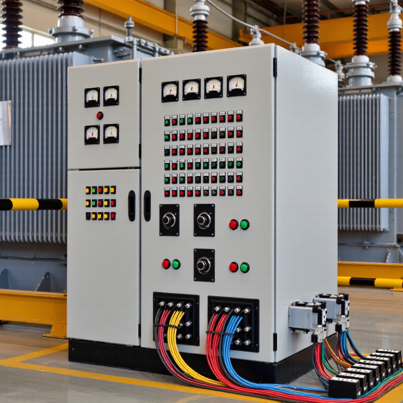
RTCC Control Cubicles provide the operating interface for an on-load tap changer. They usually contain an automatic voltage regulator, tap-position indicators, control switches, protection devices, and terminal connections. The cubicle measures transformer voltage through instrument transformers. It compares the measured value with a preset reference. If voltage moves outside the selected band, the regulator sends a raise or lower command. The tap changer then adjusts the transformer ratio, often through motor-driven mechanisms.

The process sounds simple.

It is not always simple in service.

Cable length, control power quality, incorrect settings, and mechanical wear can affect performance. Engineers typically verify alarm circuits, manual operation, interlocking, and remote signals during commissioning. IEC 60076-8 provides guidance on transformer application and voltage regulation, while IEEE C57.131 addresses on-load tap-changer application considerations. These references support disciplined design, but site conditions still matter.

A well-designed RTCC cubicle gives operators clear information at the control panel. They can see the active tap position, automatic or manual mode, and abnormal conditions. However, a cubicle should not be treated as a complete solution by itself. Protection coordination, communication reliability, maintenance access, and transformer condition must also be reviewed. Small omissions can create costly misunderstandings. This article explains the main components, control sequence, safety considerations, and practical operating limitations of an RTCC control cubicle.
What Is an RTCC Control Cubicle and How Does It Work?

Definition and Purpose of an RTCC Control Cubicle

An RTCC control cubicle is an electrical control enclosure used with a transformer’s on-load tap changer. RTCC means Remote Tap Changer Control. Its purpose is simple: keep the outgoing voltage near a selected value while demand changes. The cubicle receives voltage and current signals from the transformer system. It then commands the tap changer to raise or lower the transformer ratio.

Inside, operators may find a voltage regulator, selector switches, meters, relays, terminal blocks, and alarm circuits. These parts allow local control and remote supervision. A trained technician can set voltage limits, time delays, and control modes during commissioning. Clear wiring labels matter. One misplaced signal can cause unwanted tap movement or a false alarm. The cubicle also helps operators monitor conditions without approaching the transformer frequently.

Tips: Check control power before testing the tap changer. Confirm the voltage sensing circuit first. Review alarm settings after maintenance. Keep the door sealed against dust and moisture. Never assume the displayed voltage is correct without comparing it with a calibrated meter. An RTCC cubicle is useful, but it is not a complete protection system. That distinction is easy to overlook. Its performance depends on accurate sensors, sound wiring, and careful settings. Periodic inspection should include terminal tightness, insulation condition, heater operation, and manual control response. Controls can fail quietly.

What Is an RTCC Control Cubicle and How Does It Work?

An RTCC (Remote Tap Changer Control) cubicle monitors transformer secondary voltage and operates the on-load tap changer to keep the bus voltage close to its nominal value. The representative values below show how automatic tap adjustment can reduce voltage variation as transformer loading increases on a 400 V system.

Main Components Inside an RTCC Control Cubicle

What Is an RTCC Control Cubicle and How Does It Work?

Main Components Inside an RTCC Control Cubicle

An RTCC control cubicle manages a transformer’s on-load tap changer from a protected panel. It senses voltage through instrument transformers, compares readings with a preset value, and sends raise or lower commands. This keeps secondary voltage stable when demand changes. The cabinet usually contains an automatic voltage regulator, tap-position indicator, manual and automatic selectors, raise and lower pushbuttons, control relays, timers, miniature circuit breakers, and terminal blocks.

Communication modules may transmit voltage, current, tap position, and alarm status to a supervisory system. Protection circuits can report motor failure, loss of control supply, excessive tap movement, or a mismatch between the commanded and actual tap positions. The International Energy Agency reported in Electricity Grids and Secure Energy Transitions that global grid investment must exceed 600 billion dollars annually by 2030. Better monitoring inside cubicles supports that expansion, although control quality still depends on correct wiring and commissioning.

Tips: Keep power and signal wiring physically separated. Label every terminal clearly. Test manual operation before enabling automatic control. Check the regulator’s sensing range against transformer data. A tidy panel helps, but it does not prove reliable operation. Field teams should also verify alarm delays, interlocks, and communication loss. Small omissions can create confusing tap movements later. An independent inspection is worth the extra time.

How RTCC Control Cubicles Monitor and Control Equipment

An RTCC control cubicle is a dedicated enclosure for monitoring and controlling transformer tap-changing equipment. It usually receives signals from voltage transformers, current transformers, temperature sensors, and the on-load tap changer. These signals show whether the transformer is operating within its permitted range.

Inside the cubicle, a controller compares the measured voltage with a preset target. If voltage drops, it can send a raise command to the tap changer. If voltage rises, it can issue a lower command. Interlocks prevent unsafe operations, such as repeated commands or movement beyond the tap limits. Operators can use local switches, an HMI, or a remote control system.

Clear feedback matters. The panel should display tap position, operating mode, alarms, motor status, and control power health. It may also record failed operations, abnormal temperature, or communication loss. During commissioning, technicians test every indication and command separately. Small wiring errors can create confusing alarms.

Good practice includes electrical isolation, labelled terminals, surge protection, and routine inspection. A cubicle can appear healthy while a sensor is drifting. That risk deserves attention. Manual control remains useful during testing or communication failure, but it requires trained personnel and approved procedures. —

Communication, Protection, and Automation Functions

An RTCC control cubicle is the operational nerve center of a substation or industrial power system. It houses remote terminal units, protection relays, communication interfaces, power supplies, and terminal blocks. Through fiber, Ethernet, or serial links, it exchanges measurements and commands with a control center. Operators can view voltage, current, breaker status, and alarms without standing beside high-voltage equipment.

Communication is only one function. Protection relays detect faults and issue rapid trip commands when current or voltage exceeds safe limits. Automation logic can transfer feeders, isolate failed sections, or restore service after a disturbance.

The IEA’s Electricity 2024 report forecasts global electricity demand growth of about 4% annually from 2024 through 2026. That growth increases the need for dependable monitoring and faster operational decisions.

Practical commissioning often reveals small weaknesses. A loose terminal, poor grounding point, or outdated configuration can delay a correct response. The cubicle should include tested signal lists, time synchronization, event recording, and clear alarm priorities.

NERC’s 2024 State of Reliability report continues to emphasize changing grid conditions, protection performance, and the operational risks created by evolving resources. Cybersecurity also matters, because communication ports can become control paths.

No RTCC design is perfect. Engineers should review failed tests, not hide them, and verify every automatic action under realistic fault conditions.

Installation, Maintenance, and Safety Considerations

What Is an RTCC Control Cubicle and How Does It Work?

An RTCC control cubicle usually manages a transformer’s on-load tap changer. It receives voltage signals from instrument transformers and compares them with the preset value. The controller then sends raise or lower commands to the tap-changer motor. Interlocks block unsafe operations, while alarms report failures, low oil levels, or abnormal voltage. Communication ports can also send status data to a substation control system.

Installation needs careful attention to wiring, grounding, ventilation, and cable separation. Control cables should remain away from high-current conductors where practical. Each terminal must match the approved schematic. One overlooked terminal can create false indications or unwanted tap movement. The U.S. Energy Information Administration reports that transmission and distribution losses remain close to 5% of delivered electricity in recent data. Reliable voltage control can help limit avoidable network losses, although it cannot solve poor transformer loading.

Maintenance should follow a documented plan under NFPA 70B:2023. Technicians should inspect terminals, heaters, relays, fuses, motor drives, and communication links. They should also test local and remote commands under controlled conditions. IEEE 1584-2018 supports arc-flash assessment using available fault current, clearing time, and equipment details. De-energization is safer whenever feasible. Live work needs qualified personnel and defined boundaries. A clean drawing is not proof of a safe installation. Field conditions change, and maintenance records sometimes fail to reflect them.

What Is an RTCC Control Cubicle and How Does It Work? — Installation, Maintenance, and Safety Considerations

Reference data for a Remote Tap Changer Control (RTCC) cubicle used with a transformer on-load tap changer. Actual ratings, wiring, protection settings, and procedures must be confirmed against the transformer and tap-changer manufacturer documentation and the applicable electrical code.

System Area Data Dimension Typical Data or Requirement How It Works or Is Used Installation, Maintenance, and Safety Considerations
Purpose Primary function Remote control and automatic regulation of transformer tap position The cubicle receives voltage measurements, compares the measured value with a set point, and sends raise or lower commands to the tap-changer drive mechanism. Confirm that the RTCC control philosophy matches the transformer protection scheme, operating procedure, and substation control system.
Transformer Interface Controlled equipment Transformer on-load tap changer, commonly installed on the high-voltage or neutral end of a transformer winding The tap changer changes the effective turns ratio while the transformer remains energized and carrying load, within its specified operating limits. Never issue a tap command unless the tap-changer type, control voltage, interlocks, and available tap range have been verified.
Voltage Measurement Voltage transformer input A scaled AC voltage signal from a voltage transformer or approved sensing circuit The regulator uses the measured bus or line voltage to determine whether a tap increase or decrease is required. Use correctly rated fuses or miniature circuit breakers, provide test links where required, and verify polarity, phase sequence, and isolation facilities.
Current Compensation Load-current input Current transformer signal, where line-drop compensation or circulating-current compensation is required The controller can calculate an estimated remote-end voltage or coordinate parallel transformers using current and voltage information. Never leave an energized current-transformer secondary open-circuited. Use shorting terminals and follow approved CT isolation procedures.
Control Logic Voltage regulation Set point, bandwidth, time delay, and tap limits configured for the transformer application A dead band prevents unnecessary tap movement. A time delay prevents the controller from responding to brief voltage disturbances. Settings should be approved by the responsible protection or power-system engineer. Record every setting change and its authorization.
Operating Modes Control selection Local manual, local automatic, remote manual, and remote automatic modes, as applicable Mode selection determines whether commands originate from the cubicle, an automatic regulator, or a remote supervisory control system. Provide clear mode indication and a secure local/remote selector. Prevent simultaneous local and remote commands through electrical interlocking.
Tap Position Position indication Mechanical or electrical tap-position indication with a defined minimum, neutral, and maximum position The RTCC displays the present tap and can transmit it to a supervisory control system through hardwired or digital signals. Check agreement between the cubicle indication, the drive mechanism, and the remote indication. Investigate any position mismatch before further operation.
Command Outputs Raise and lower commands Two separate interlocked outputs for tap raise and tap lower A momentary command energizes the appropriate motor-control circuit in the tap-changer drive mechanism. Electrical and mechanical interlocks must prevent raise and lower contactors from closing at the same time. Verify command duration and end-limit operation.
Motor Supply Drive mechanism power AC or DC supply selected to match the tap-changer motor and control equipment The RTCC control circuit operates contactors, relays, or a motor-control assembly that supplies the tap-changer drive motor. Verify voltage, frequency, short-circuit protection, earthing, cable size, and voltage drop. Keep control and power wiring properly segregated.
Control Supply Auxiliary control voltage Commonly a low-voltage AC or DC supply, such as 24 V DC, 48 V DC, 110 V DC, or 230 V AC, depending on the design The supply powers the regulator, indication lamps, relays, communication equipment, and control circuits. Label all sources clearly. Provide isolation and overcurrent protection, and verify that stored energy is removed before maintenance.
Automatic Regulation Dead band and delay Application-specific voltage dead band and intentional time delay The regulator initiates a tap change only when voltage remains outside the permitted band for the configured delay period. Excessively narrow settings can cause hunting and accelerated tap-changer wear. Excessively wide settings can allow unacceptable voltage deviation.
Tap Limits Upper and lower travel limits Defined by the tap-changer nameplate and transformer voltage-ratio requirements Limit switches and software or relay logic stop commands before the mechanical end of the permitted tap range. Test limit switches and end-position indication during commissioning and scheduled maintenance. Do not bypass travel limits during normal operation.
Parallel Operation Transformer coordination Master-follower or circulating-current control, only when transformers are suitable for parallel operation Coordination logic keeps parallel transformers at compatible tap positions and minimizes circulating current. Confirm matching ratio, vector group, impedance, phase sequence, and compatible tap-changer characteristics before enabling parallel control.
Communication Remote monitoring interface Hardwired contacts or an industrial communication link, subject to the substation control design Status, alarms, tap position, voltage, current, and operating mode can be transmitted to a supervisory system. Use shielded and correctly terminated communication wiring where required. Test loss-of-communication behavior and ensure remote commands fail safely.
Alarm Functions Typical alarm points Control-supply failure, motor overload, tap-position disagreement, out-of-band voltage, drive fault, and remote/local status Alarms alert operators to abnormal conditions that may prevent automatic regulation or indicate a tap-changer problem. Test each alarm from the field device to the operator interface. Define alarm priorities and avoid disabling alarms without authorization.
Enclosure Protection rating An ingress-protection rating selected for the installation environment; the rating must be verified for the actual site The enclosure protects control equipment from accidental contact, dust, moisture, and mechanical impact to the extent specified by its rating. Maintain door seals, cable glands, drainage, ventilation, and corrosion protection. Do not drill or modify the enclosure without restoring its environmental rating.
Internal Layout Component segregation Separate power, control, instrumentation, and communication wiring where required by the design Segregation reduces electrical interference and makes testing, fault finding, and isolation safer. Use terminal identification, ferrules, wire numbers, barriers, and an updated wiring diagram. Keep spare terminals and unused conductors safely terminated.
Earthing Protective earth connection A dedicated protective-earth connection bonded to the cubicle frame and metallic doors Earthing provides a low-impedance fault-current path and helps keep exposed metalwork near earth potential. Inspect earth-bonding conductors and door-bonding straps. Verify continuity and comply with the site earthing design before energization.
Installation Mounting and location A dry, accessible, ventilated location with sufficient clearance for operation and maintenance Correct positioning protects the cubicle from excessive heat, vibration, water ingress, and unauthorized access. Install on a rigid, level support. Maintain working clearance, provide adequate lighting, and keep the front of the cubicle unobstructed.
Commissioning Pre-energization checks Visual inspection, insulation checks where appropriate, point-to-point wiring verification, functional tests, and interlock tests Commissioning confirms that measurements, commands, indications, alarms, and protective functions operate as intended. Use approved test procedures. Isolate primary equipment as required, confirm test-equipment ratings, and document test results and final settings.
Maintenance Routine inspection Periodic inspection based on operating conditions, duty cycle, environmental exposure, and the maintenance program Inspection identifies loose terminals, overheating, contamination, corrosion, failed lamps, damaged wiring, or abnormal relay operation. De-energize and isolate before internal work. Apply lockout/tagout, prove dead with an approved tester, and discharge stored energy.
Maintenance Tap-changer service Service interval determined by tap operations, load current, oil condition where applicable, and the tap-changer manual The tap-changer is a mechanical switching device and may require inspection, contact maintenance, oil checks, or mechanism adjustment. Do not treat the RTCC cubicle as a substitute for tap-changer maintenance. Follow the specific service procedure and operation counter records.
Safety Electrical isolation Isolation of transformer, voltage-transformer circuits, current-transformer circuits, control supply, motor supply, and remote command paths as applicable Multiple energy sources can remain present even when the cubicle appears to be switched off. Identify all sources, isolate them, lock and tag them, test for absence of voltage, and control remote or automatic reclosing functions.
Safety Arc-flash and shock risk Risk level depends on system voltage, prospective fault current, clearing time, and the equipment design A fault inside the cubicle can release hazardous electrical energy and may cause burns, blast pressure, or flying debris. Complete a site-specific risk assessment. Use the required boundaries, arc-rated clothing, eye and face protection, insulated tools, and qualified personnel.
Safety Automatic operation hazard Tap movement may occur without local manual action when automatic or remote mode is selected The regulator can issue a command after a voltage deviation and time delay, even when an operator is working near the mechanism. Select a safe mode, inhibit automatic operation where authorized, and verify that remote commands are blocked before inspection or testing.
Documentation Required records Single-line diagram, wiring diagram, terminal schedule, settings sheet, test records, alarm list, and maintenance history Accurate records allow safe operation, efficient troubleshooting, and controlled future modifications. Keep drawings and settings current inside the document-control system. Record changes, test dates, personnel, measured values, and corrective actions.

Important: The values shown are typical engineering references rather than universal ratings. The transformer nameplate, tap-changer documentation, approved protection settings, electrical design, local regulations, and site safety procedures always take precedence.

FAQS

What does an RTCC control cubicle do?

It monitors and controls a transformer’s on-load tap changer. It receives voltage, current, temperature, and tap-position signals. The controller compares measured voltage with a preset target. It can send raise or lower commands when voltage changes.

How does the cubicle respond to voltage changes?

A voltage drop may trigger a raise command. A voltage rise may trigger a lower command. The controller sends commands to the tap-changer motor. The response depends on configured limits and operating conditions.

What safety features prevent unwanted tap movement?

Interlocks block repeated commands and movement beyond tap limits. They can also prevent actions during unsuitable operating conditions. Manual control requires trained personnel and approved procedures. Small errors spread.

What information should appear on the control panel?

The display should show tap position, operating mode, and motor status. It should also indicate alarms and control-power health. Useful alarms include failed operations, high temperature, and communication loss. Feedback matters.

What should technicians check during commissioning?

Technicians should test every indication and command separately. They should verify local, remote, and manual control functions. Each terminal must match the approved wiring diagram. A single wiring error can create confusing alarms.

What installation details support reliable operation?

Installers should provide proper grounding, ventilation, and labelled terminals. Control cables should remain separated from high-current conductors where practical. Surge protection can help protect sensitive control components. A tidy panel is not automatically a safe panel.

What maintenance does an RTCC cubicle need?

A documented maintenance plan should guide inspections and testing. Technicians should inspect terminals, heaters, relays, fuses, motor drives, and communication links. They should also check for loose connections and damaged wiring. A sensor can drift while the cubicle appears healthy.

When is manual control appropriate?

Manual control can help during commissioning or communication failure. Only qualified personnel should operate it under controlled conditions. Electrical isolation is safer whenever feasible. Field conditions change, and records may not show every change.

Conclusion

An RTCC Control Cubicle is a centralized electrical and automation enclosure designed to monitor, control, and protect power distribution equipment. It typically contains control switches, monitoring instruments, relays, circuit protection devices, terminal blocks, power supplies, and communication interfaces. These components work together to collect operating data, display system conditions, and send control commands to connected equipment, helping operators manage electrical systems safely and efficiently.

RTCC Control Cubicles also support communication, protection, alarm handling, and automatic control functions. They can detect abnormal conditions such as overloads, faults, or loss of supply and initiate suitable protective actions. During installation, proper wiring, grounding, ventilation, labeling, and environmental protection are essential. Regular inspection, testing, cleaning, and functional checks help maintain reliable performance. Maintenance personnel should follow approved procedures, isolate power before servicing, and use appropriate safety equipment to reduce operational risks.

Liam

Liam

Liam is a dedicated marketing professional with a keen expertise in the company's product offerings. With a background steeped in strategic marketing and consumer engagement, he consistently demonstrates a profound understanding of market trends and customer needs. Liam takes pride in creating......
Download Brochure Chat on WhatsApp