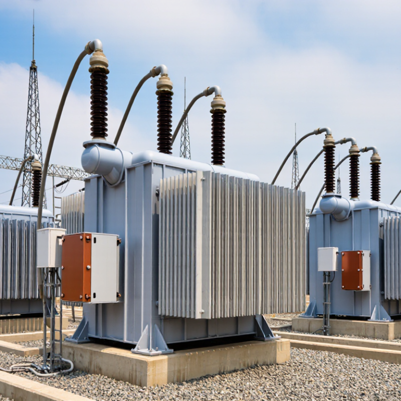
| Two-Winding Power Transformer |
66 kV to 550 kV |
10 MVA to 1,000+ MVA |
Transmission substations, utility grids, large industrial substations, renewable-energy collection systems |
Simple system integration, dependable voltage transformation, broad availability of standardized designs |
Impedance selection, short-circuit withstand, tap-changer range, transport limitations, grid-code compliance |
Mineral-oil or ester-liquid insulated; ONAN, ONAF, OFAF, or ODAF cooling depending on rating |
Utilities and heavy industry |
| Autotransformer |
110 kV to 800 kV |
100 MVA to 1,200+ MVA |
Interconnecting transmission networks with closely related voltage levels, bulk-power substations |
Lower material usage, smaller footprint, lower losses, and potentially lower cost than an isolated two-winding design |
No galvanic isolation between windings; fault levels, neutral grounding, insulation coordination, and voltage ratio must be carefully assessed |
Oil-immersed construction with forced-oil and forced-air cooling for high ratings |
Transmission network operators |
| Three-Winding Transformer |
66 kV to 550 kV |
30 MVA to 500 MVA |
Substations serving transmission, distribution, auxiliary-service, and industrial loads from one transformer |
Connects three voltage levels while reducing the need for separate transformer banks and minimizing substation space |
Complex impedance relationships, tertiary-winding loading, fault-current coordination, and thermal balancing |
Oil-immersed, typically with ONAN/ONAF or higher-capacity forced cooling |
Multi-voltage substations |
| Phase-Shifting Transformer |
110 kV to 500 kV |
100 MVA to 1,000 MVA |
Power-flow control, congested transmission corridors, cross-border interconnections, and loop-flow management |
Controls active-power flow and improves utilization of existing transmission assets without building an entirely new corridor |
Mechanical and electrical complexity, high short-circuit forces, tap-changer duty, protection coordination, and system studies |
Oil-immersed; commonly uses forced cooling and on-load tap changers |
Grid planners and transmission utilities |
| Generator Step-Up Transformer |
11 kV to 765 kV |
50 MVA to 1,200+ MVA |
Hydroelectric, thermal, nuclear, wind, and utility-scale solar power plants |
Raises generator voltage for efficient long-distance transmission and supports high continuous loading |
Generator terminal fault duty, high insulation stress, transport route, zero-sequence behavior, and harmonic exposure |
Oil-immersed; ONAN/ONAF for moderate ratings and OFAF/ODAF for large units |
Power-generation projects |
| Renewable-Energy Main Transformer |
33 kV to 550 kV |
20 MVA to 500 MVA |
Wind farms, photovoltaic plants, battery-energy-storage facilities, and hybrid renewable parks |
Supports variable generation, high daily load cycling, collector-system integration, and grid-code requirements |
Frequent load changes, harmonics from power electronics, acoustic limits, ambient conditions, and rapid energization requirements |
Mineral-oil or natural/synthetic ester; sealed-tank or conservator designs with suitable forced cooling |
Renewable project developers |
| Rectifier Transformer |
Up to approximately 220 kV primary voltage |
10 MVA to 500+ MVA |
Aluminum and copper smelting, electrolysis, hydrogen production, industrial drives, and chemical processing |
Designed for high-current rectifier loads, low-voltage high-current output, and demanding harmonic environments |
Harmonic heating, DC magnetization, leakage reactance, short-circuit forces, phase-shift configuration, and cooling redundancy |
Oil-immersed with high-capacity forced-oil or water-cooled heat exchangers where required |
Process-industry operators |
| Furnace Transformer |
Up to approximately 220 kV primary voltage |
10 MVA to 300+ MVA |
Electric arc furnaces, ladle furnaces, ferroalloy plants, steel mills, and non-ferrous metal production |
Handles high-current, rapidly fluctuating loads and provides low-voltage output suitable for furnace operation |
Electrodynamic forces, voltage regulation speed, harmonic distortion, thermal cycling, and very high secondary currents |
Oil-immersed with forced cooling; on-load tap changing is common for voltage control |
Metals and steel producers |
| Mobile Emergency Power Transformer |
66 kV to 345 kV |
20 MVA to 200 MVA |
Temporary grid restoration, disaster recovery, planned substation outages, and emergency replacement capacity |
Rapid deployment, reduced outage duration, modular transport options, and flexible temporary interconnection |
Road and rail transport limits, compact design, fast installation, site grounding, and compatibility with existing protection systems |
Oil-immersed; compact radiator banks and transport-resistant accessories are commonly used |
Utilities requiring resilience |
| Dry-Type High-Voltage Transformer |
Up to approximately 72.5 kV |
1 MVA to 40 MVA |
Indoor substations, offshore platforms, commercial infrastructure, tunnels, data centers, and locations with fire or spill restrictions |
No liquid leakage risk, reduced fire hazard, simplified indoor installation, and lower routine environmental impact |
Higher purchase cost at large ratings, ventilation requirements, altitude derating, noise control, and thermal management |
Cast-resin or vacuum-pressure-impregnated insulation; natural-air or forced-air cooling |
Indoor and environmentally sensitive sites |
| Mobile Substation Transformer |
66 kV to 245 kV |
20 MVA to 200 MVA |
Temporary distribution capacity, mining operations, remote infrastructure, construction projects, and grid maintenance |
Flexible deployment, reduced civil works, and the ability to serve temporary or remote loads |
Transportable dimensions, seismic requirements, harsh-environment protection, grounding design, and commissioning time |
Oil-immersed with compact cooling equipment and reinforced transport fittings |
Remote and temporary power users |